If you have followed our articles so far on how the pins work on an Arduino, how to calculate resistor sizes, and how to use the Arduino IDE – it’s time to take the first plunge into LED’s and get some blinky lights going!
Not All LED’s Are The Same
LED’s function like a Diode. They only allow voltage one direction, if reversed at smaller voltages, they will do nothing and remain unharmed. When voltage flows in the right direction however it causes the LED to emit light.
With that said, different diodes and LED’s can handle different voltages and currents. This is actually true even for RGB LED’s between the red, green and blue streams. That means what works for one LED isn’t always a perfect match for a different LED.
Working with Breadboards

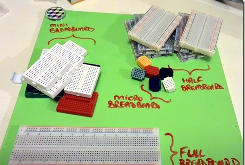
There are many different types of breadboards, and breadboards sometimes do not behave exactly like regular printed circuit boards. This is because breadboards have metal plates that result in some resistance and can sometimes result in bad connections.

The most common breadboard is probably a half-sized breadboard. This is what you see in the photos below. it has power and ground channels that run up the left and right hand side. Please note that the left side power channels are not connected to the right side.
However, in the middle, the connections run in a row or series. This means 1a, 2b, 2c, 2d, 1e are connected. However, the gap separates 1f, 1g, 1h, 1i, 1j which are on their own. This is perfect for resistors to split the two sides of the resistor, and for IC’s, where you may be splitting out pins later on.
Symbol, Sample and Information

Above shows you the standard symbol for an LED and how we will be connecting it for this tutorial.
In this example, connect the LED to the Arduino by:
- Connect your Grounding Pin to the LED short leg
- Connect one side of your resistor
Turning on an LED
How this works is simple. Remember that an Arduino Uno pushes out 5V. This goes to the positive pin of the LED with a resistor as a buffer. You can then run the negative pin of the LED to ground.
When the voltage is enabled, is running the right direction, and the current flow is protected, it will turn on an LED.


Once you have your LED connected properly (see above for more connection examples) you can use the following code to upload to your Arduino! Once the code finishes uploading, the Arduino should restart, and the LED will start blinking!
Code:
int LEDPin = 3; // what PIN are you using for your simple ON / OFF 2 prong LED?

void setup() {
  // Setup your pins here
  pinMode(LEDPin, OUTPUT);
}

void loop() {

  // Digital ON / OFF
  digitalWrite(LEDPin, LOW);
  delay(150);
  digitalWrite(LEDPin, HIGH);
  delay(150);

  // Faux Analog OFF > ON
  for(int i=0; i< 255; i++) {
    analogWrite(LEDPin,i);
    delay(2);
  }

  // Faux Analog ON > OFF
  for(int i=0; i< 255; i++) {
    analogWrite(LEDPin,255-i);
    delay(2);
  }

}
Get the code from Github!
Related Articles:
3 thoughts on “Arduino – Working with LEDs”