This short tutorial will show you how to get started using multicoloured LED’s with Arduino. Specifically common anode and common cathode and to control the red, blue and green separately. This means multicoloured blinky lights! And later, you will be able to see a sample of how to control this with Wi-Fi.
Difference Between Anode and Cathode
Anode is another way of saying positive. And cathode is another way of saying negative (or grounding in our case). When an RGB has a “common anode” it means instead of making you use 6 pins (3 RGB in and 3 RGB out) we are only going to use one side as a set of 3 and share the other. This reduces the number of pins you need to use.
In the world of Arduino, outside of how you run your wires and write your code, Anode versus Cathode makes no real difference. They both use up the same amount of voltage.
But think of a Common Anode as the LED is sharing its positive (5v) pin with 3 grounding pins for RGB. Where-as a Common Cathode means the LED is sharing its negative (GND) pin with 3 x 5v pins for RGB.
Common Anode

Above shows you the symbols and connection we will be using controlling a Common Anode RGB LED. You may notice as well, as we cover more and more topics, the builds require less explanation.


Connect the LED to the Arduino by:
- Connect your longest leg to a 330 ohm resistor
- Connect the other side of the resistor to the 5V pin on the Arduino
- Connect the other 3 RGB LED pins to pins 9, 10 and 11
- Note: These are PWM pins, you can fade these in and out for better control!
Once you have completed this, jump down to the code below to test your RGB LEDs. If you experience issues, or are using Common Cathode RGB LED’s please read the section below.
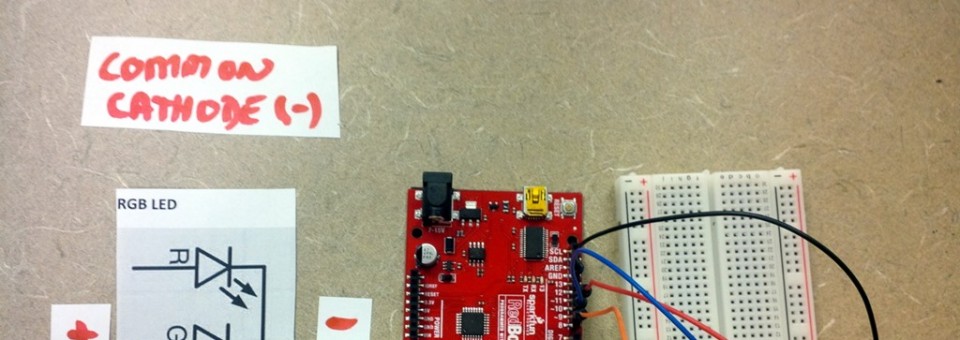
Common Cathode

If the Anode instructions did not work for you, or if you have a Common Cathode RGB LED, use the following instructions to get setup.


Connect the LED to the Arduino by:
- Connect your longest leg to any GND pin on the Arduino
- Connect the other 3 pins to one side of 3 separate 330ohm resistors
- Connect the other side of those resistors to pins 9, 10 and 11
- Note: These are PWM pins, you can fade these in and out for better control!
When your in a pinch, and doing a small build this, you can actually get away with using a single 330 ohm resistor on the grounding pin, its just generally bad practice (as you want the resistor to always be protecting the LED from the power source side). This way, in case there is an accidental grounding, the unit will not burn out the LED.
Code:
Double check your connections, this same stretch of code will work the same on both Anode and Cathode (more or less – it will just be inverted). Just remember to switch from grounding to voltage (or in reverse) and to move your resistors to follow your power.
int RPIN = 9;  // what PIN are you using for RED?
int BPIN = 10; // what PIN are you using for BLUE?
int GPIN = 11; // what PIN are you using for GREEN?

void setup() {
  // put your setup code here, to run once:
  pinMode(RPIN, OUTPUT);
  pinMode(BPIN, OUTPUT);
  pinMode(GPIN, OUTPUT);
}

void loop() {
  // Digital ON / OFF (cycles)
  digitalWrite(GPIN, LOW);
  digitalWrite(RPIN, HIGH);
  delay(150);
  digitalWrite(RPIN, LOW);
  digitalWrite(BPIN, HIGH);
  delay(150);
  digitalWrite(BPIN, LOW);
  digitalWrite(GPIN, HIGH);
  delay(150);

  // Fade in Red
  for(int i=0; i< 255; i++) {
    analogWrite(RPIN,i);
    analogWrite(255-GPIN,i);
    delay(2);
  }
  // Fade in Blue
  for(int i=0; i< 255; i++) {
    analogWrite(BPIN,i);
    analogWrite(255-RPIN,i);
    delay(2);
  }
  // Fade in Green
  for(int i=0; i< 255; i++) {
    analogWrite(GPIN,i);
    analogWrite(255-BPIN,i);
    delay(2);
  }

}
Get the code from Github!
Related Articles:
hey man I’m freaking out over here. ((last sentence asks the question, everything else is background information of the problem)) I wrote code to make an rgb cathode have the color green fade from off to max brightness, then blue would fade from off to max brightness, on after to other, then they would fade back down to off and repeat. it worked successfully but not that i tried the wiring setup provided for an anode rgb led, its causing problems with the outcome of the code. the code only runs on the anode rgb when the “blue” pin is plugged in, but I wrote the code with information coming out of two pins (for the cathode setup). do you have ay idea why my code works perfectly fine on a cathode rgb but not anode?
Hmm, the only thing between them in their polarity is reversed and instead of a common shared positive it’s a common shared negative. Any chance it’s a bad LED?