For users brand new to Arduino, the pin system can be a little bit confusing. So I thought covering them in a very high level detail may help before we get too far. By the end of this tutorial set, you will be able to use input and output on an Arduino. And you should have a good understanding of resistors and LEDs.
How are the Pins Laid Out Again?
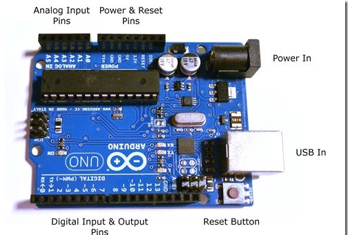
Not including pins such as clock, reset or serial – the main pins used by most people are shown below. We will go into these pins in more detail in a moment.

What are PINs Used For Again?
Pins on an Arduino (or most any development board for that matter) can do two things. They can supply voltage, or act as a grounding wire. This is used to create electrical changes or to sense electrical changes.
Remember my “do this, then that” analogy? Well that’s what the pins are for. They act as your sensors (buttons, trimpots, etc) and your generators (buzzing, motors, LEDs). That isn’t to say it can’t do a whole lot more – using Serial and Software Serial you can stretch this to all kinds of things such as Wi-Fi and Cellular data control.
Digital versus Analog

Digital In and Digital Out are absolute values. It is either on or it is off, it is not in the middle.
Analog is across a spectrum, typically 0 to 255. It is used for faders, trimpots, and other elements that can live in the in-between state. Arduino is a funny beast, it accepts Analog In, but we have to trick devices to use Analog Out.
What is PWM? (PINs with a ~ prefacing the number)
PWM (Arduino’s form of ‘analog out’) pin’s are capable of acting as digital input, digital output or ‘analog output’. However, PWM is actually a really, really fast digital pulse called Pulse Wave Modulation. What it does, is it turns it on and off so fast that it ‘seems’ to fade.
In order to use true analog out on an Arduino, you actually have to use capacitors and resistors to delay your current.
Input versus Output

Input is what we use for input devices. Such as buttons and switches. Input typically triggers the reaction.

Output is what we use for audio, LCD’s, LED’s and other related devices. It is also typically what we want to invoke as a result of an action.
You can change a pin from Input to Output very easily in your code.
Writing Code for Pins
How do we control these input and output devices in the Arduino IDE? To do this, we need to better understand how the IDE works.
void setup() {
  // put your setup code here, to run once:
}

void loop() {
  // put your main code here, to run repeatedly:
}
Above shows you the generic code that is automatically generated by the Arduino IDE for every program.
These are two ‘functions’ that are always used, and always reserved, by the Arduino IDE. A function is a series of commands (‘if this then that’) and occur in sequence when called. You want to create functions anytime you are planning to do the same thing twice.
void function_name() {
}
In plain English, this is saying:
Variable_Type_To_Return Function_Name (Variables_You_Specify) { Actions to Perform }
Great, but what is setup() and loop()?
Setup is automatically launched when the Arduino finishes initializing (like every time you restart the Arduino). The loop is what is run over and over again after! So setup is good for your initial checks and loop for your ‘if this then that’ code.
Specifying Pin Types
First things first, we know that one pin can have multiple purposes. So the first thing we want to do, usually only once, is to specify if the pin is being used for input or output
void setup() {
    pinMode(PIN#, INPUT [or OUTPUT]);
}
For example: pinMode(3,OUTPUT); tells the Arduino to care about sending voltage out on pin 3. Where-as pinMode(3,INPUT); tells the Arduino to care about what voltage is coming in on pin 3. If this is a Digital Pin that means it is on 5v or off (HIGH or LOW). If this is an Analog Pin that means it is expecting a value between 5v and 0v and can cover a range.
Using Pins in Code
There are two ways we will be turning on pins:
digitalWrite(PIN, HIGH/LOW);
analogWrite(PIN, 0/255);   // only works with PWM, more on this later
And two ways we will be listening on pins:
digitalRead(PIN);  // is the pin HIGH or LOW?
analogRead(PIN); // a value between 0 and 255 (5V)
This will get more important later on! For now, this concludes our section on understanding the Arduino Pins.
Related Articles:
3 thoughts on “Arduino – Understanding the Pins on the Arduino”