I recently ordered a large shipment of PCB boards from a company some of you may have heard called SparkFun.
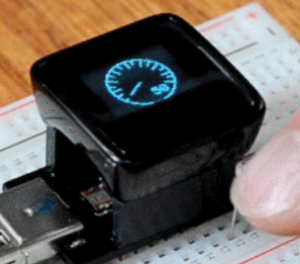
Besides getting a whole bunch of cool boards, I made one additional unnecessary purchase: A DIY Digital Oscilloscope Kit.
See the video here:
My Rating: Medium Difficulty – Not for Beginners (But Totally Fun!)
Parts & Tools:
The unit comes as a cohesive kit – meaning it is a single purchase of 80 dollars plus shipping.
With that said, there are a few tools you need from around your house.
- 12V Power Supply – I get mine on eBay for a few dollars (I buy a LOT of power supplies).
- Multimeter (for testing step # 9)
- A screw driver (for case assembly and regulator)
- A soldering iron with a fine tip
- Some solder
- A set of cutters
- And its nice to have some pointy head pliers for the regulator bending and holding hot things
It looks to be a resale of products from another company called jyetech, where all the instructions and information provided are from jyetech themselves. It looks like they even have a kit that you do the SMD work yourself.
Assembly:
Full assembly only took around 1 hour and 15 minutes. It was fairly straightforward, but the instructions are not clear in a few areas. Additionally, some of the instructions are open to interpretation, and would be difficult for new users.
How I assembled it:
First thing to do is take everything out. Unlike some projects, you actually will end up just dumping the bag of parts on the counter.
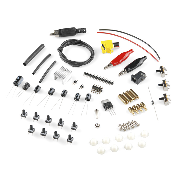
[Note: Photo borrowed from SparkFun, *without* permission. Yeah thats how I roll!]
Phase 1: Backboard Assembly
![]()
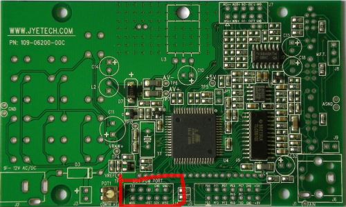
Step 1: Installing Diode D3 (Warning watch the polarity)
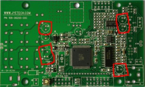
Step 2: Installing Capacitors (Warning watch the polarity)
![]()
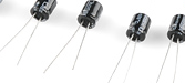
Step 3: Install inductor L2
Note: This is the strange rubber capacitor looking thing.
![]()
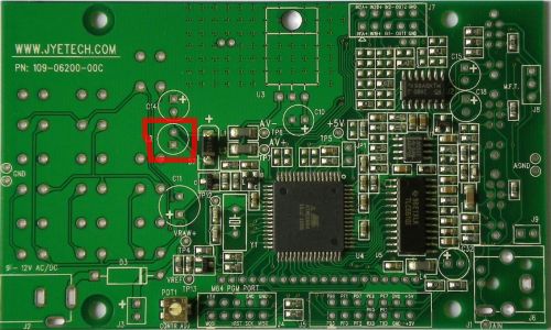
Step 4: Install header on J4
Note: When you install this header, the “long” part of the legs point up towards you.
Note #2: This is an ultra handy programming header. So, you know, you can hack this to run PONG if you really wanted to.

![]()
Step 5: Install power connector on J2


Step 6: This where you install your BNC or AV connector (Note: SparkFun will come with an AV connector – the yellow thing)
Step 7: I skipped this step complete, as it wasn’t done on their final diagram.

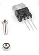
Step 8: Install voltage regulator U3 and its heat sink
Note: This uses the only long screw in the package.
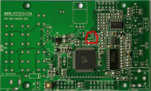
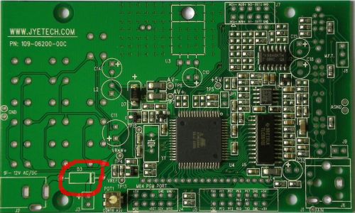
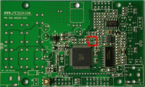
Step 9: Power check
Note: When checking the power supply, you need to reference TP5. Its hard to find (above).
Step 10: Close the loop on JP1
Note: I just took one of the cut-off capacitor pieces and made a U shape
Phase 2, Working on the Front LCD Face
Note: The following items are fairly clear, so I won’t add separate photos for them.
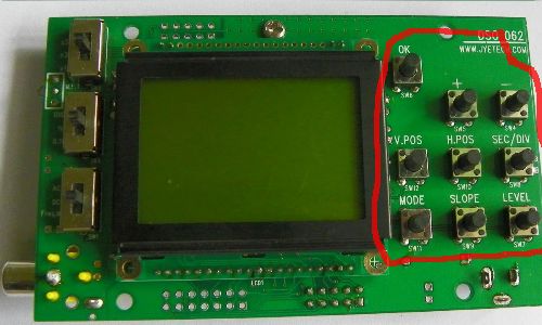
Step 11: Tact Switches
Note: I had no problems with these, but the documentation advises the soldering is in close proximity in the back.
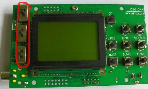
Step 12: Slide Switches
Note: These were actually much, much harder to install. This is why a fine tip soldering iron is handy.
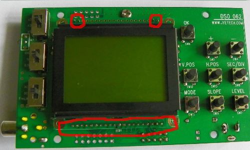
Step 13: Installing the LCD
The final LCD step is shown above, it wasn’t too difficult to finalize. It mentions cutting the leads on some of the pins, but they were too short for me to bother with.
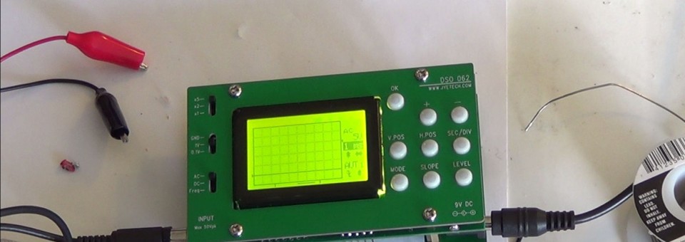
Closing the Case
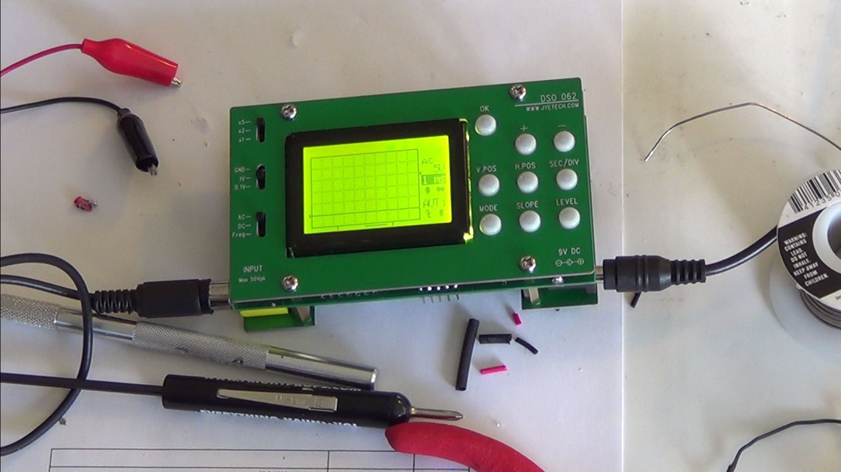
And that is it! Closing up the case is pretty easy, add your little white buttons. And use the screws on the “outside” of the case, to hold all the guts together, and your done!
On an unrelated note…
checkout their latest kickstarter. Yeah, I ordered 2 of those and time is running out!